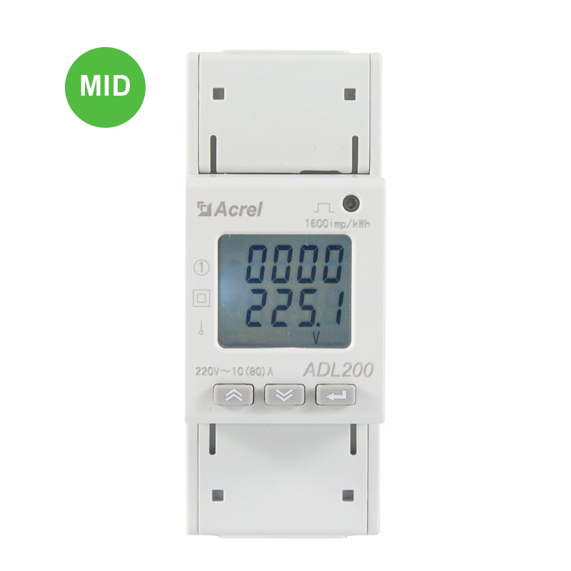
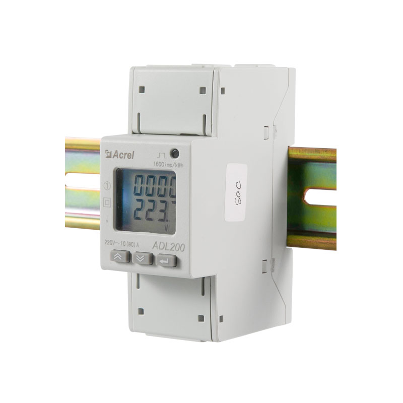
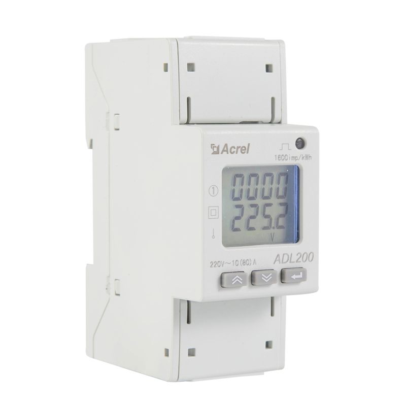
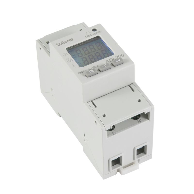
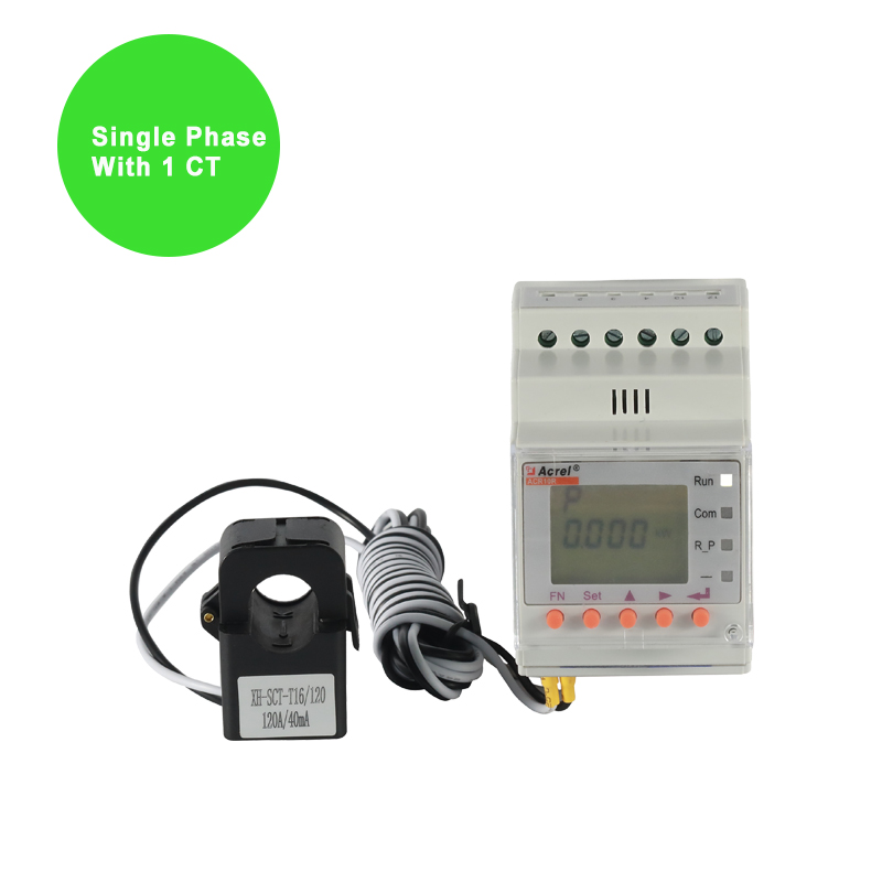
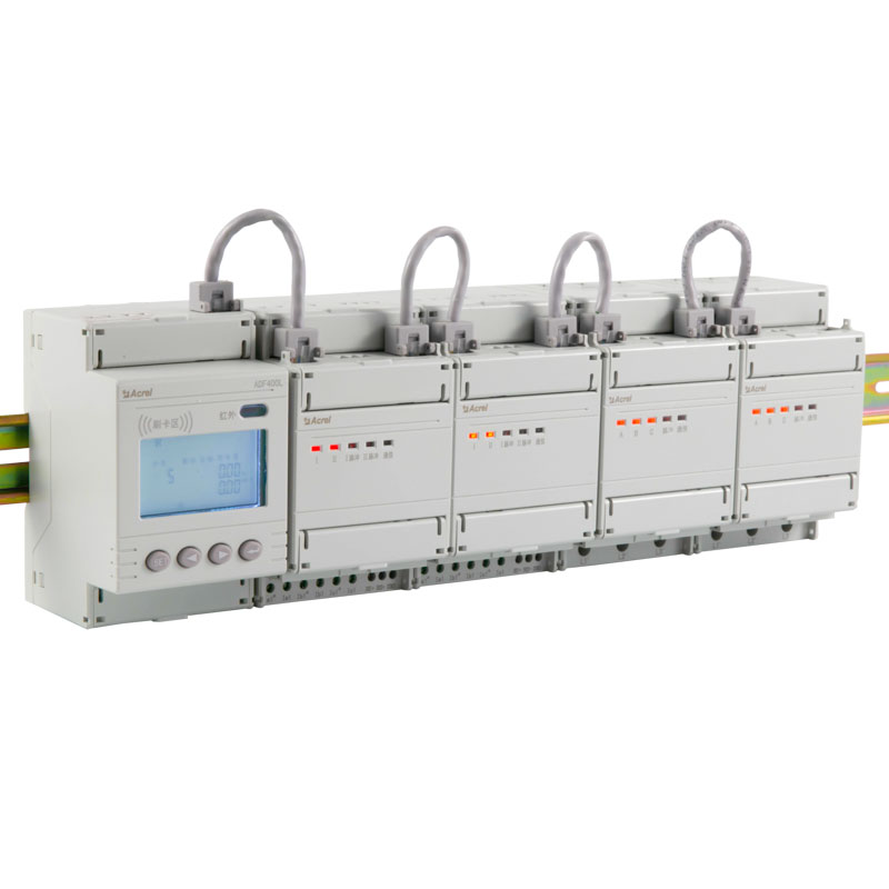
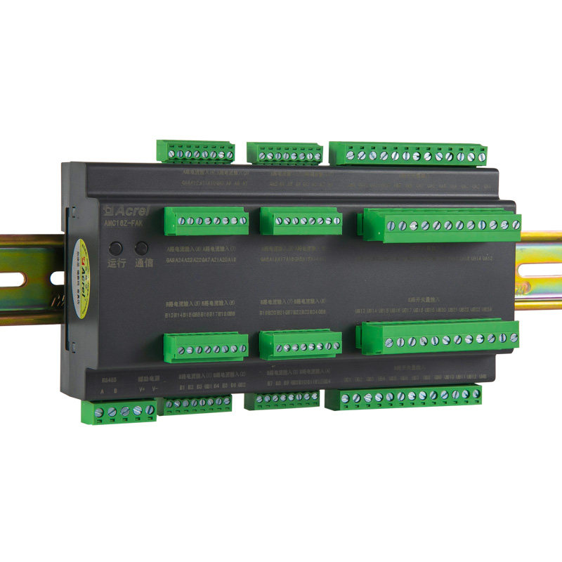
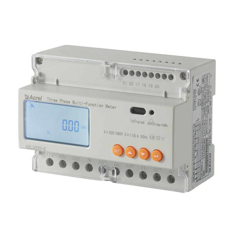
Modbus Meter ADL200 Single Phase Din Rail Energy Meter
● Rated Voltage: AC220V
● Rated Current: 10(80)A
● RS485(MODBUS-RTU) Communication
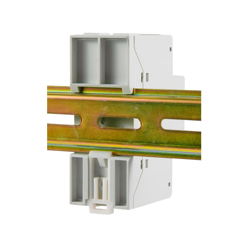
● LCD Display; 35mm DIN Rail Installation
● Multi-tariff: 4 Tariff Rates (Spike, Peak, Valley and Flat kWh)
● kWh Class 1
- Overview
- Parameter
- Certificates
- Customer Questions & Answers
- Contact us
Application
Cabinet Installation Household Meter Box Power Distributor Room |
|
Mall And Supermarket School Building |
|
Overview
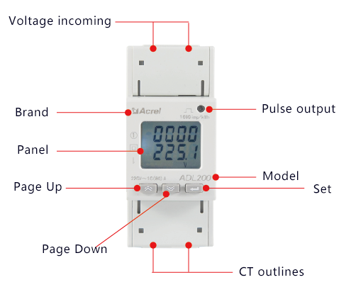
ADL200 Single Phase Electric Energy Meter adopts DIN35mm din rail installation with LCD display,it can measure electric parameters and has energy pulse output, RS485 communication,which has the advantages of small size, high precision, good reliability and convenient installation.
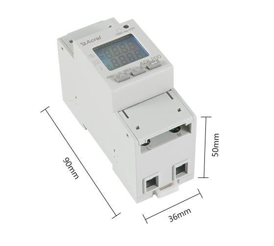
Dimension
Functions
| Kwh Meter 1 Phase ADL200 Electricity Measurement:U,I,P,Q,S,PF,F Voltage:AC220V Current:Lower 80A Direct Connect Communication:RS485,Modbus-RTU |
Display

Installation
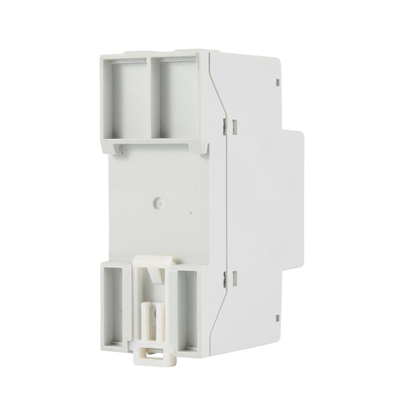
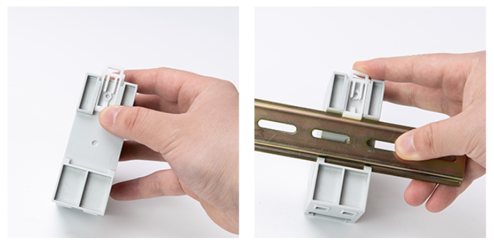
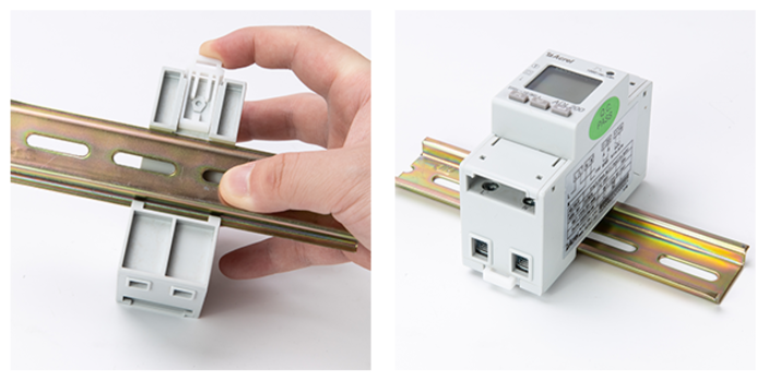
1.Push away the buckle on the back of the meter 2.Install on 35mm Din rail |
3.Push up the buckle 4.The meter could be fixed |
Network

| Input voltage | Reference voltage | AC 220V |
| Reference frequency | 50Hz | |
| Power consumption | <10VA | |
| Input current | Basic current | 10A |
| Maximum current | 80A | |
| Starting current | 4‰Ib | |
| Consumption | <4VA | |
| Measurement performance | Accuracy of measuring | 1 class |
| Range of measuring | 000000.00~99999999kWh | |
| Clock accuracy | Error≤0.5s/d | |
| Active pulse | Pulse width | 80±20ms |
| Pulse constant | 1000imp/kWh | |
| Communication | Interface | RS485(A+、B-) |
| Connection mode | Shielded twisted pair conductors | |
| Protocol | MODBUS-RTU | |
Customer Questions & Answers
-
Answer:
Switch the meter display interface to the power (active power P, power factor λ) interface, and check whether the power display is negative or not.And whether the power factor is between 0.9-0.95, and then check whether the incoming and outgoing wires of the current signal wire are connected reversely (that is, the current The incoming wire must be the same as the incoming wire end of the meter), and consistent with the wiring diagram on the meter.
marry August 31, 2022
-
Answer:
1. The voltage value between the communication output A and B of the measuring instrument should be between +(4.4-4.5)V . 2. Check whether the communication wiring method is correctly wired according to the wiring diagram (that is, the communication terminal A/B of the instrument must be connected with Corresponding to communication serial port A/B);
marry August 31, 2022

 EN
EN
 ES
ES ID
ID CN
CN